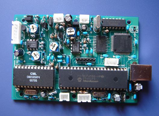
 USB connector was changed from A type to B type. Diagram of this PCB is V01.04.

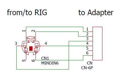 Diagram of connection between RIG and Adapter. (CN1 Pin Assign)
| 1 | Data (to RIG) |
| 2 | GND |
| 3 | PTT (to RIG) |
| 4 | 9600 bps Input (from RIG) |
| 5 | Not use |
| 6 | SQ(COS) |
| Yaese/Kenwood | ICOM | IC-208H/ID-800 | |
| SW1 | off | on | off |
| SW2 | on | off | on |
| SW3 | 2-3 | 1-2 | 2-3 |
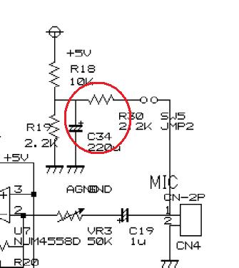
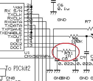
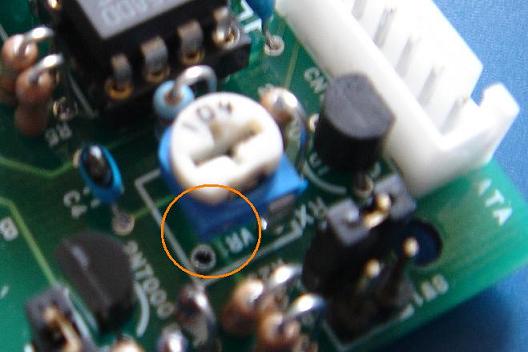 This PCB has one mistake. I forgot to float the pin one of VR1. If you will make this, please do not connect the pin one of VR1. (see red circle.)
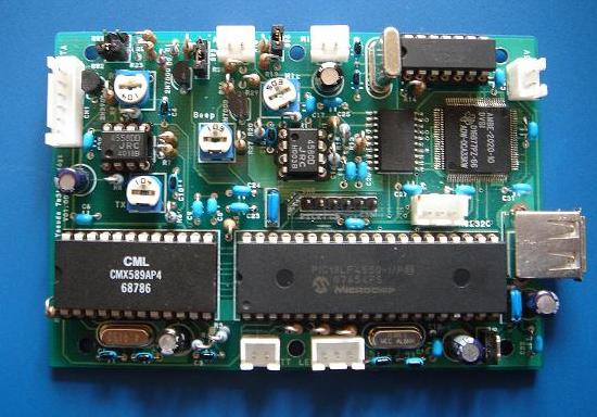
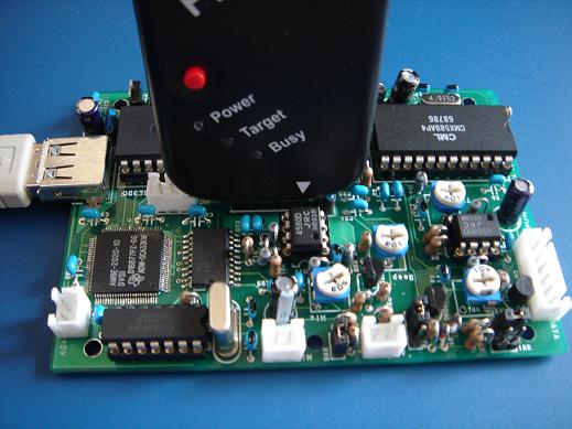 This PCB uses the PICkit2 for programing of PIC18LF4550.
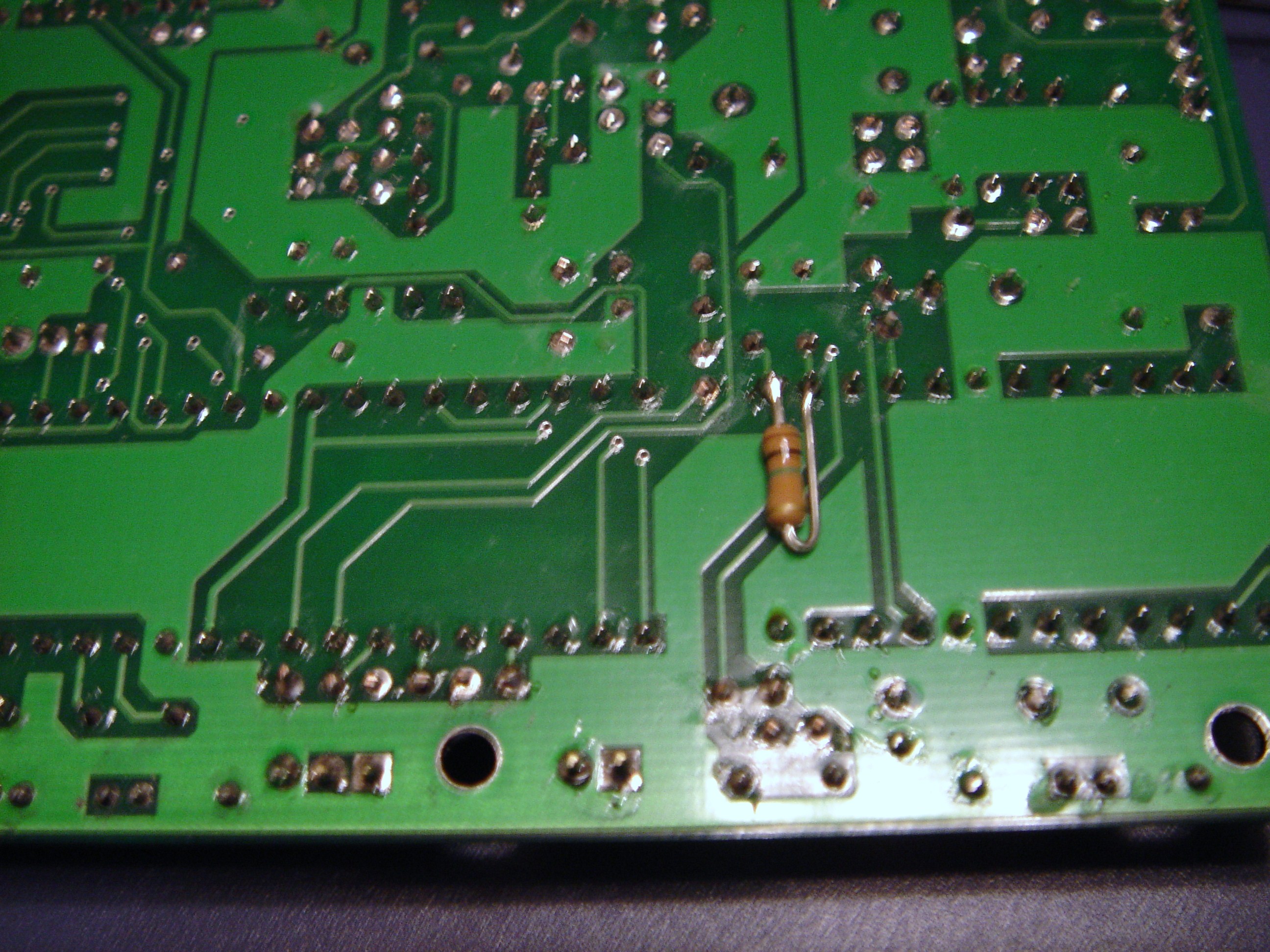
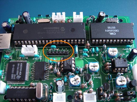 Connect (header pins) for PICkit2 (see red circle.)
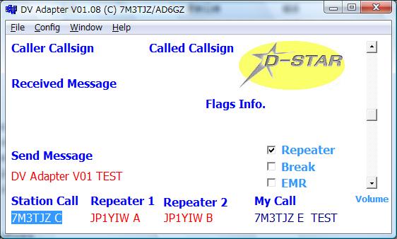 Snapshot of control progeam screen.
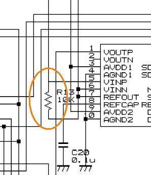 remove R13.