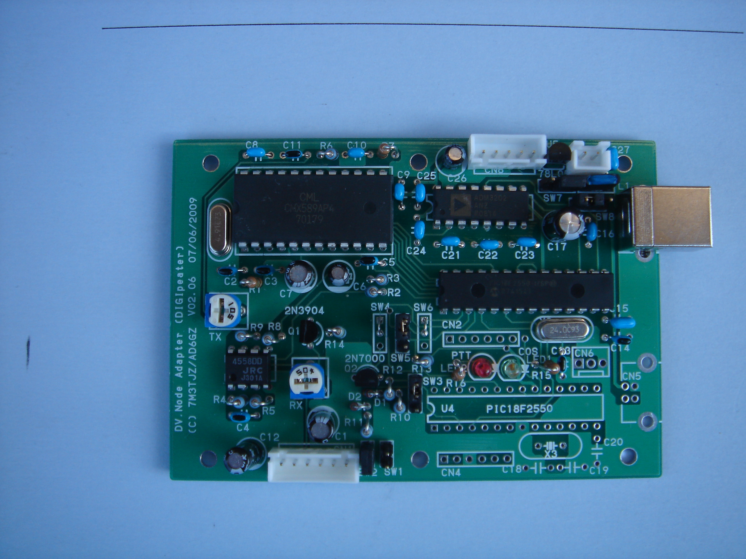
 Assembled complete parts for V06.xx
| CN1 | from/to Rig (see below) |
| CN3 | USB |
| CN6 | LED 1:COS 2:PTT 3:both GND |
| CN7 | external power from 7V to 9V (see SW7) |
| CN8 | RS232C (see SW8) |
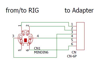
| 1 | Data (to RIG) |
| 2 | GND |
| 3 | PTT (to RIG) |
| 4 | 9600 bps Input (from RIG) |
| 5 | Not use |
| 6 | SQ(COS) |
| Yaesu/Kenwood | ICOM | IC-208H/ID-800 | |
| SW1 | off | on | off |
| SW2 | on | off | on |
| SW3 | 2-3 | 1-2 | 2-3 |
| Normal Mode | Stand alone repeater | |
| SW5 | 1-2 on | 2-3 on |
| SW4 | 1-2 on |
| SW6 | 1-2 on |
| USB Bus power | External power | |
| SW7 | 2-3 on | 1-2 on |
| TTL level | RS232C level | |
| SW8 | 1-2 on | 2-3 on |
| TTL level | 1:TX 2:RX 3:GND |
| RS232C level | 4:RX 5:TX 3:GND |
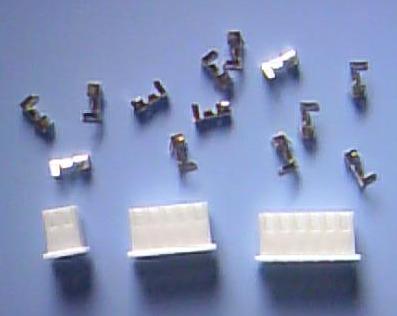 Those connecter and pin are included with the complete assembled PCB..

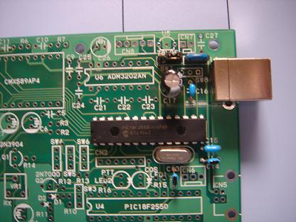
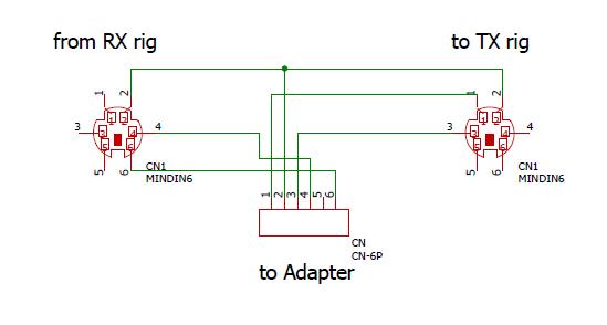 Diagram of connection between TX rig, RX rig and this adapter.